Navigating The Unknown!
Table of Contents:
- 1. Deadline
- 2. Problem Statement and Starter Code
- 3. Environment
- 4. Navigation Stack
- 5. Testing For Various Window Shapes
- 6. Testing (Live Demo) And Grading
- 7. Submission Guidelines
- 8. Allowed and Disallowed functions
- 9. Collaboration Policy
1. Deadline
11:59:59 PM, Nov 16, 2026.
2. Problem Statement and Starter Code
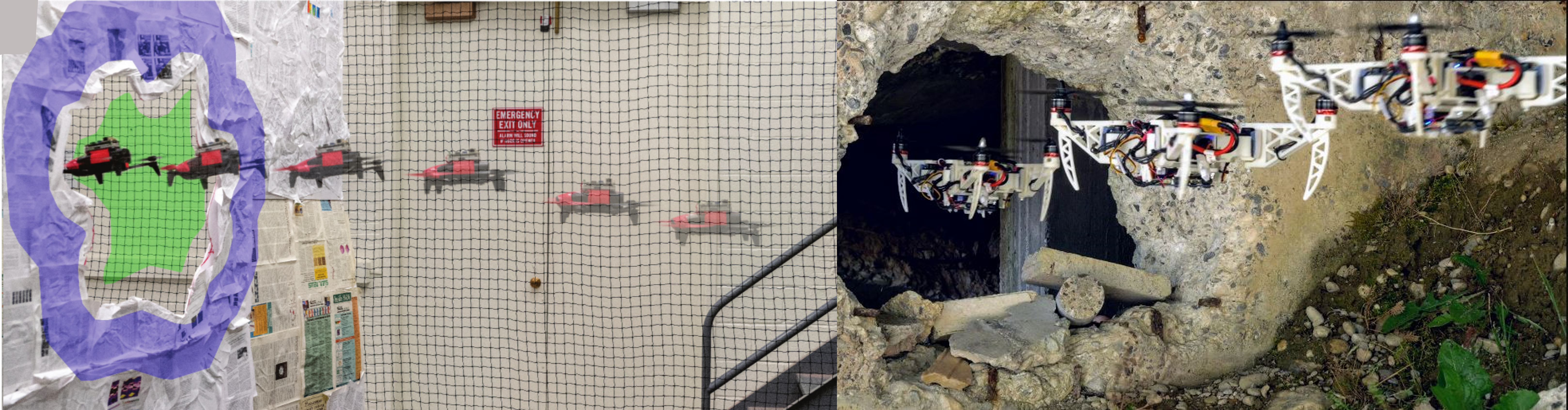
Flight through known windows is very cool and exciting but often in the real-world you have to fly through irregular and unknown shaped windows for search and rescue, exploration or reconnaissance purposes (See Fig. 1). To this end, experts in the field have developed a multitude of algorithms and approaches for building or sensing a 3D model of the world. Although this works very well, it is computationally and weight-wise prohibitive for our tiny little drones. In such a resource-constrained scenario, what can we do? Well you can think creatively, in one of the works from Prof. Sanket named GapFlyt (See Fig. 1 left), the team utilized the movement of the quadrotor to obtain additional cues for detection of the gap. The sky is the limit here (pun intended) for all the approaches you can come up with to detect a gap of unknown shape, size and location (assuming it is in the field of view) to detect it and fly through it. The project is completely open-ended and you are free to use any third party code to detect and fly though a gap of unknown shape, size and location. The only constraint is that your code has to run on the lab PC, inside the course container, within the 15 Hz loop described below, without any cloud computation during experiments.
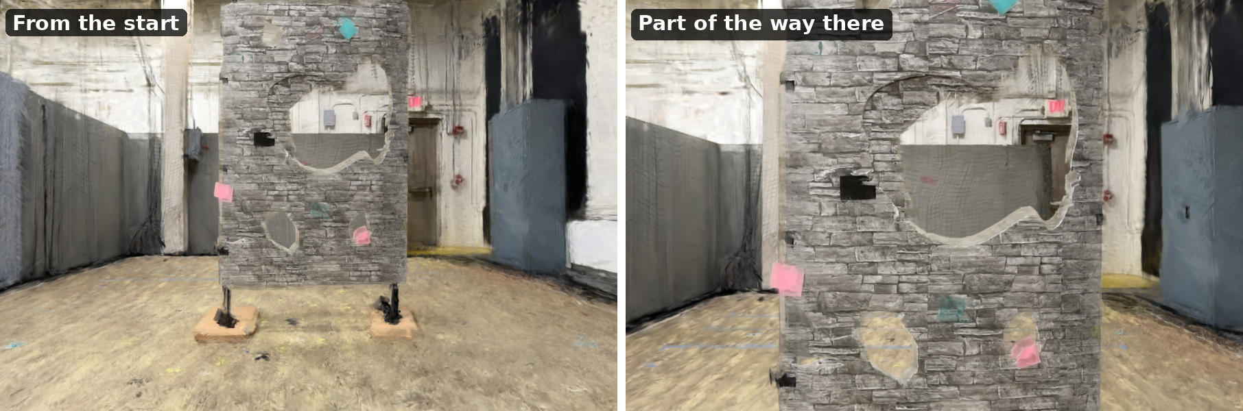
As in Projects 2b and 3, you will fly a Crazyflie in the net under motion capture, and its camera images are rendered from a Gaussian splat of the net at the drone’s pose. You will develop your stack in simulation against the A4 scene, a splat of the net with the window standing in it, and then fly the same code on the real drone, in the same scene. The starter code can be downloaded from here. The course documentation covers the setup, the simulator and flying the drone.
3. Environment
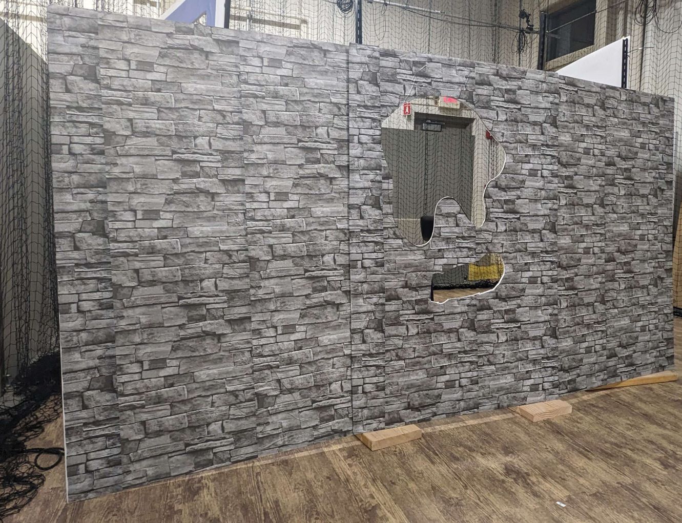
The environment has one arbitrary shaped window, standing about 3 m in front of the origin and facing it, so it can be ‘seen’ from the origin location (Fig. 3). The window is made of foamcore with a texture print stuck on it, and stands on two poles. The board can be assumed to be nearly planar and has multiple holes/gaps, in which case you’ll choose the largest one to fly through. The largest gap will be large enough for the quadrotor to fly through it safely; the smaller gaps are not. Furthermore, there is no guarantee that the gap will be at the center of the foamcore. Once you take off, you should be able to see a part of the window at least, and you might need additional exploratory maneuvers to see the entire window. Real arbitrary shaped windows are shown in Fig. 2. Flying from the side/above of the foamcore does not count as a successful navigation. You can also assume that the window shape is nearly convex.
The A4 scene is also the scene of the demo. The starter’s scene folder is a splat of the net with this window standing in it, and there is no separate test scene: you develop in this scene and fly in it. The window’s print is a stone wall, but your method should not depend on it: test it on other textures and shapes in Blender as well (Section 5). Nothing about the window or its gap may be hard-coded (Section 8).
Everything is in metres, in the Vicon frame, as in Projects 2b and 3: x runs down the course, y across it, z up, with z = 0 at the floor and the origin on the L marker taped to the floor.
The real window stands in the net where it is in the scene. Hitting the window in the scene means hitting it for real. Remember that you are flying a drone with a 75 mm radius, not a point.
Your drone carries a front-facing camera: every frame is an RGB image, rendered from the splat at 15 Hz. There is no depth in this project: unlike in Project 3, your policy gets the RGB image alone, in the simulator and on the drone. You are not allowed to change the field of view (60.66° horizontal) or the camera mount, which looks straight ahead. You choose the image resolution: set it in the starter’s tools/make_contract.py (the default is 320 × 213). To look somewhere else, yaw the drone: the yaw rate is yours to command.
The loop runs at 15 Hz on the lab PC. Each frame is rendered, handed to your code, and your command has to be back before the next frame, about 66 ms later. The rendering, your perception and your controller all share those 66 ms, and a loop that cannot keep up is stopped.
4. Navigation Stack
4.1. Perception Stack
You are free to use any method to detect and track the window to fly through it. Methods can include estimating depth (if they generalize), estimating optical flow, estimating occlusions, estimating flow uncertainty to name a few. You are allowed to use any third party code for this as long as it fits in the loop: in flight, it runs on the lab PC, inside the course container, within the 66 ms above. The container does not come with a deep learning library: if you need one (for example PyTorch or ONNX Runtime), add it in your own layer on top of the container, as docker/example-student.Dockerfile in cf_vicon_stack shows.
4.2. Planning and Control Stack
You are free to use any method to generate waypoints to fly through the window. The drone’s position comes from Vicon and you may use it, as in Projects 2b and 3, but where the window and its gap are must come from your perception stack: your code may not read the window’s geometry from the scene files, or any window fields of the state your policy is given. Those are there to check your perception and to score your runs, not to fly by.
Your controller is the velocity loop from Projects 2b and 3: your policy returns a velocity command, plus a yaw rate if you want to turn. The planner around it could be something simple like a hierarchical task planner (such as a state machine) or a 3D planner such as RRT*. The controller again can be 3D waypoint following or simple alignment on the image plane. The design choice is all yours. The goal is to fly through the gap that you can fit through safely without any collisions.
A robot that collides will be considered a FAIL and you will get a ZERO.
5. Testing For Various Window Shapes
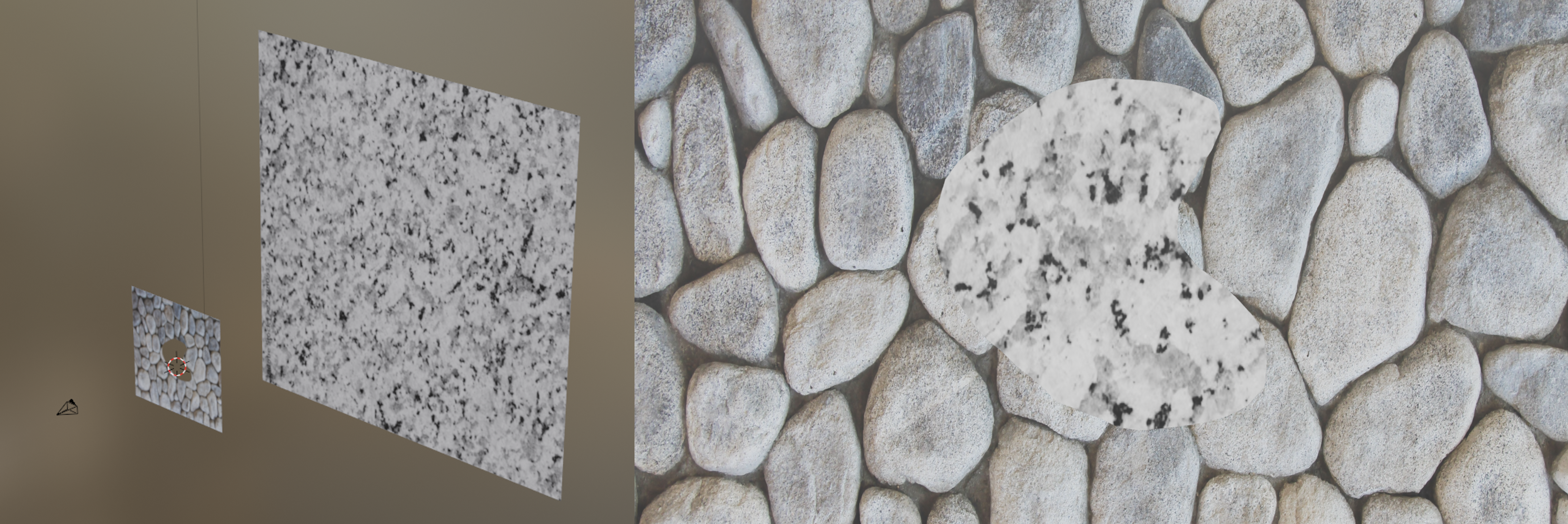
Testing on real-data with various arbitrary window shapes can be hard. Hence, to enable fast prototyping, we want you to test on four arbitrary window shapes and present the results in your report along with the live demo (more details in the next section). The four arbitrary windows are given in the Blender folder of the starter code. You can move the camera as you wish in this case as required by your algorithm either through code or using animations and change the window textures to any image for your testing (we have included four example textures for you to experiment with in the Blender/Assets/Textures folder). The window shapes are produced by an Alpha mask where white color represents foreground and black color represents background (feel free to create any shapes you want for testing). The masks for windows are given in the Blender/Assets/Windows folder. You need to run the Blender/Window.blend file to experiment in simulation. You need to compare your detection results with the ground truth mask obtained using Pass Index (set to 2 in the blend file) and saved in the Blender/Outputs/GTMasks folder using the Intersection over Union (IoU) metric. Furthermore, if you want to change the window textures or cutout shape, you have to go to the Shading editor tab on the top and change the respective textures: Mask node for the window cutout mask, ImageFg node for the foreground texture (on the window plane) and ImageBg node. An example environment and one of its rendered image are shown in Fig. 4.
6. Testing (Live Demo) And Grading
Each team will be given a 15 minute slot for demoing their code in action to the instructors. You will fly in the A4 scene, the one in the starter, with the real window standing in the net where it is in the scene. As in Projects 2b and 3, you will do a dry run first and then fly the real drone. The quadrotor will be placed at the origin, facing the window, and hovers at 0.7 m before your policy takes over. The task is to fly through the gap as fast as possible without any collisions. You can get as many attempts as you want to accomplish this within your 15 minute time slot, and each run ends after 2 minutes. Your final grade for the demo is decided based on completion (successful flight through the gap) and time.
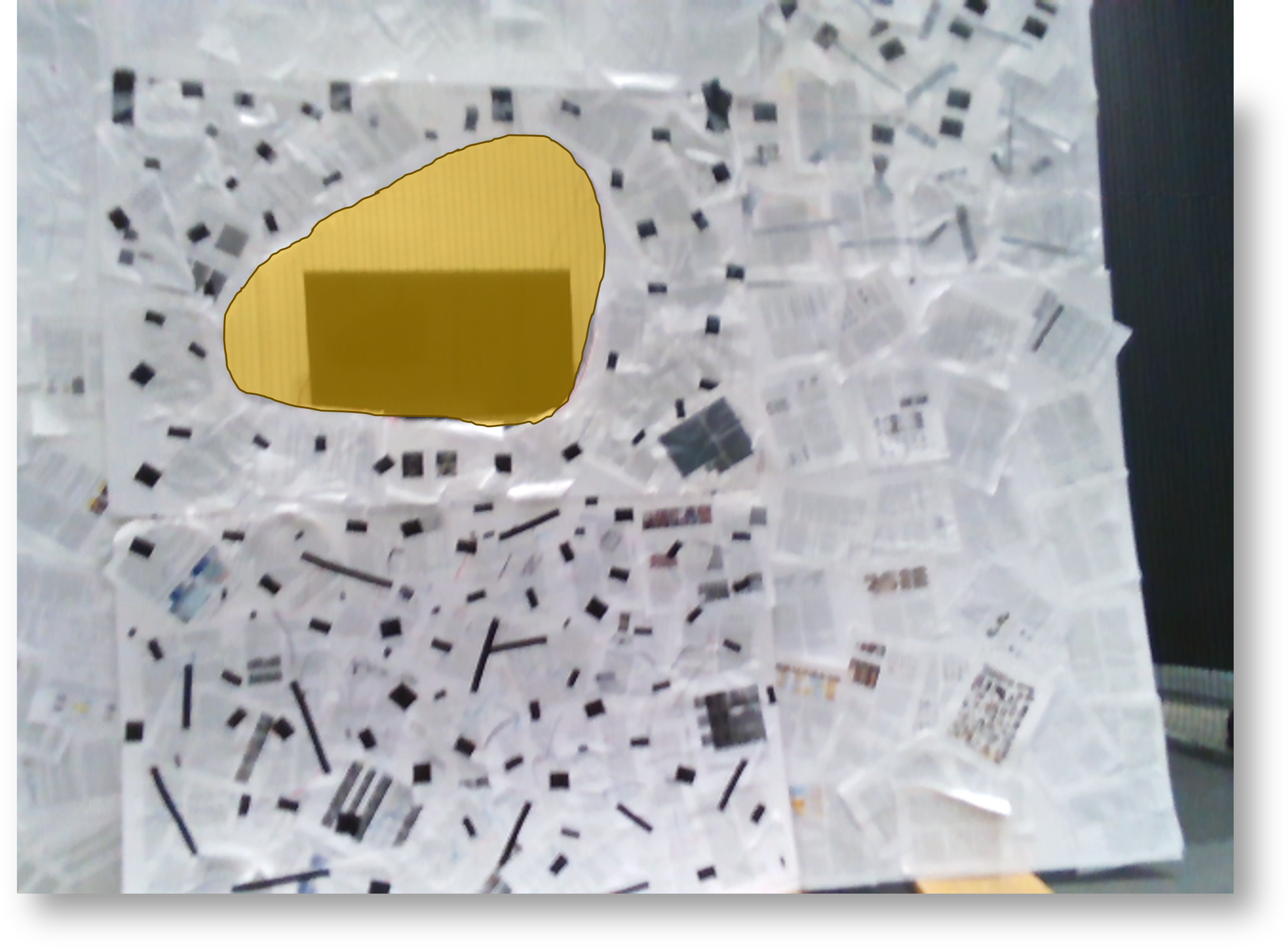
You are required to show us a detection of the gap as an overlay as shown in Fig. 5 when you fly through it. Save the camera view with your detections during the run and play it back afterwards: the display does not have to be live, but the detection does. Optionally you can also show us a visualization of the tracking of the gap.
7. Submission Guidelines
If your submission does not comply with the following guidelines, you’ll be given ZERO credit.
7.1. File tree and naming
Your submission on ELMS/Canvas must be a zip file, following the naming convention p4_GroupGROUPNUM.zip. Find your group number on Canvas. If your GROUPNUM is 1, then for our example the submission file should be named p4_Group1.zip. The file must have the following directory structure. The file to run for your project should be called p4_GroupGROUPNUM/Code/Wrapper.py: it runs your stack in the simulator. On the drone, tools/fly.py from the starter (ros_node with the depth taken out) flies your policy class; say which one in README.md. You can have any helper functions in sub-folders as you wish, be sure to index them using RELATIVE paths, never absolute ones – your code has to run on a machine that is not yours, and an absolute path from your laptop will not resolve on the grader’s. If you have command line arguments for your Wrapper codes, make sure to have default values too. Please provide detailed instructions on how to run your code in README.md file.
NOTE: Please DO NOT include data in your submission. Furthermore, the size of your submission file should NOT exceed more than 500MB.
The file tree of your submission SHOULD resemble this:
p4_GroupGROUPNUM.zip
├── Code
|   ├── Wrapper.py
|   ├── policy.py
|   ├── perception.py
|   ├── control.py
|   ├── weights/          <- only if your method needs them
|   └── Any other helper modules you wrote
├── Blender
|   ├── Window.blend
|   └── Other supporting files
├── Report.pdf
├── FPVVideo.mp4
├── RunVideo.mp4
└── README.md
Submit only what you wrote, plus any trained weights your code needs. Do not include the starter pack, the scene
(splat, ESDF, point cloud), any training data, or any flight logs – they will push you past the size limit. Your
Wrapper.py should take the path to the scene as a command line argument, with the starter’s scene as a sensible
relative default.
7.2. Report
For each section of the project, explain briefly what you did, and describe any interesting problems you encountered and/or solutions you implemented. You must include the following details in your writeup:
- Your report MUST be typeset in LaTeX in the IEEE Tran format provided to you in the
Draftfolder and should of a conference quality paper. Feel free to use any online tool to edit such as Overleaf or install LaTeX on your local machine. - Results of testing on the four arbitrary window shapes provided in Blender.
7.3. Video
Record the FPV video (the drone’s camera view) of your run in .mp4 format and submit it in the zip file. Make sure to name it as FPVVideo.mp4. This video should include the raw footage and your gap detection overlay side by side. Use the maximum resolution possible here for the best quality.
Record the same run on the real drone in .mp4 format, during your demo or before it, and name it RunVideo.mp4. Record the video in the highest resolution with minimum being 1080p at 30fps.
8. Allowed and Disallowed functions
Allowed:
- Any functions regarding reading, writing and displaying/plotting images in
cv2,matplotlib - Basic math utilities including convolution operations in
numpyandmath - Any functions for pretty plots
- Quaternion libraries
- Any library that perform transformation between various representations of attitude
- Any code for alignment of timestamps
- Any code for data handling, network setup and architecture engineering
- Any code for estimation of 3D poses from 2D images
- Any code for data augmentation and similar functionality
- Any third party code with the correct citation
- Rendering the given splats to test your stack
Disallowed:
- Other student’s code in class
- The depth image, or any depth from the splat or the scene’s files, in your flight code
- Reading the window’s geometry from the scene files, or any window fields of the policy state, in your flight code
- Hard-coding anything about the window or the gap
- Training on images rendered from the splat: they are for testing
If you have any doubts regarding allowed and disallowed functions, please drop a public post on Piazza.
9. Collaboration Policy
NOTE: You are STRONGLY encouraged to discuss the ideas with your peers. Treat the class as a big group/family and enjoy the learning experience.
However, the code should be your own, and should be the result of you exercising your own understanding of it. If you reference anyone else’s code in writing your project, you must properly cite it in your code (in comments) and your writeup. For the full honor code refer to the RBE595-F02-ST Fall 2026 website.